Search This Blog

Sunday, August 19, 2018

60+ NEED-TO-KNOW APPLIANCE MAINTENANCE TIPS


The following article is taken from the SEARS guide (60 Appliance Maintenance Tips from Sears).
Routine maintenance is the best way to get the most out of your appliances. You probably know you should clean the lint filter every time you use the dryer and change the HVAC air filter regularly. But there are several other important things you should do to help keep your home safe and your appliances running strong.

These maintenance tips can help lower utility bills, save time and energy, increase safety and extend the life of your appliances.

FRIDGE MAINTENANCE TIPS 

1.- Check the temp.

Refrigerator temperatures fluctuate seasonally. Place a thermometer in the center of the middle shelf (not on the door). Be sure food is stored safely below 40°F.

TIP: Sometimes refrigerators don’t operate properly because the room they’re in is too hot or too cold. Keep that in mind, especially as the weather heats up or cools off dramatically.

2.- Don’t block airflow.

Improper ventilation around the outside of a fridge will cause increased energy usage and possible early equipment failure.

3.- Don’t overcrowd.

You need airflow inside as well to make sure all foods are equally cooled. Avoid the urge to stack items or cram in too many containers.

4.- Inspect the door gaskets for tears, gaps or air leakage.
If not sealed correctly, the fridge will run longer than normal, increasing energy use and raising the temperature inside the refrigerator.  

5.- Clean the condenser coil regularly. 

Dirty condensers increase the energy needed to operate the fridge and can cause early failure. Clean the coil with a brush or vacuum, just be sure to unplug the fridge first. 

6.- Change the water filter.
Don’t ignore the filter indicator when it says it’s time for replacement. Filters pushed past their limits can no longer fully trap contaminants.

OVEN AND STOVETOP MAINTENANCE TIPS

1.- Unplug the oven before cleaning. 

If it’s accessible, it’s a good idea to unplug your oven before cleaning the interior by hand. This is especially important if you’re using water. 

TIP: Use vinegar, baking soda and water to make a DIY oven cleaner.


2.- Be careful cleaning the knobs.    

This mistake is one of the major reasons for oven service calls. If you spritz cleaning fluid under the knobs, you’re essentially spraying the oven’s electrical system. That’s not safe!
TIP: You can clean the knobs themselves by pulling them off and popping them in warm soapy water.

3.- Deep clean the grates.

Spray grates with oven cleaner, put them in a plastic bag and let it sit for 24 hours. Then wash the grates with soap and water.
4.- Self clean.

Check your owner’s manual for more information and detailed instructions.

5.- Check the gas line when you get a new oven.

Your installer can check your gas line and replace it if needed when installing the new oven. You don’t want gas leaking into your kitchen.
DISHWASHER MAINTENANCE TIPS

1.- Clean your dishwasher with vinegar. 

Pour 2 cups of vinegar in the bottom of the dishwasher and run a cycle. Mid-way through, stop it for 15-20 minutes to let the vinegar work its magic, and then continue with the cycle.

TIP: To prevent damage, use a spray or wipe made for stainless steel to clean the outside of the dishwasher.
2.- Eyeball the holes in the spray arms.

If debris is clogging any of them, use a toothpick or needle nose pliers to clear them but be careful not to scratch the arms!

3.- Soak the filter.

Some dishwashers have a removable filter on the bottom. Soak it in soapy water for a bit, rinse it off and pop it back in.

4.- Wipe around the dishwasher door seal.
Use a vinegar and water solution and a rag (or even a soft toothbrush).

5.- Tackle mold with bleach.

Fill your detergent holder with bleach and run a cycle in your empty dishwasher.

TIP: Don’t use bleach with any other cleaners — especially not vinegar — and if your dishwasher’s interior is stainless, check your owner’s manual.

WASHER MAINTENANCE TIPS

1.- Inspect the hoses. 

Every month or so, make sure there are no bulges or cracks and that the fittings are tight. 

2.- Don’t overload it.

This can damage washer, so break up laundry into smaller loads.

3.- Use the right type of detergent.
Make sure you’re using the right kind for your model. Many energy-efficient washers require a low-sudsing HE detergent.

4.- Use the right amount of detergent.

Too much detergent will leave a residue and can be hard on your washer. Pods make it easy, but if you’re using liquid, measure according to the manufacturer’s directions.
5.- Clean the interior and the dispensers.

Yes, you need to wash the washer to help keep it clean and smelling fresh.

TIP: Every month or so, run an empty load of hot water with 2 cups of white vinegar. In the middle of the wash 

6.- Wipe down the drum, door and gasket.

A monthly cleaning helps ensure the washer won’t give off odors that can seep into your laundry.

7.- Leave the door ajar after a load.

Ever notice a smell when you open your washer to start a load?  Letting it air dry can help prevent odors.

8.- Transfer clean laundry to the dryer as soon as it’s done. 

Letting wet clothes languish in the washer can cause mold and mildew.
DRYER MAINTENANCE TIPS

1.- Clean the exhaust vent at least once a year.

Remove the vent from the back of the dryer and clear out any built-up lint.

2.- Check the vent cap outside.

It’s common for debris, dirt or snow to build up around the vent. Clear it out every so often to let the air flow freely.

3.- Don’t overload it.

Large loads take longer to dry and use more energy. And if clothes don’t dry completely, you may end up with a musty smell.

4.- Deep clean your lint screen.

Don’t just clean it after every load, wash it every three months.

TIP: Use a bit of laundry detergent and rinse it thoroughly or pop it in the dishwasher to clear residue left by dryer sheets.

5.- Clean out the lint trap.

Remove the screen and use a dryer lint brush to clean inside the trap itself.  Lint can build up there, too.

6.- Replace vinyl or plastic exhaust vents with metal.

Plastic exhaust vents are more likely to catch fire. Play it safe with metal.

7.- Clean the inside.

Give the inside a wipe down with a microfiber cloth and a bit of rubbing alcohol to remove any dryer sheet residue. Let it dry thoroughly. 

HVAC MAINTENANCE TIPS

1.- Give it a checkup twice a year.

Have an expert do a preventive maintenance check in the spring and fall to look for motor or electrical failures.

2.- Replace the filter every few months. 

Change it out, even if it doesn’t look dirty. Any buildup reduces the amount of air the system draws in.

3.- Clear outside debris.

Cut or remove plants that are encroaching on your condenser so it can pull in fresh air from all sides. Make sure to allow for at least 12 inches of space around the coil.

TIP: Turn off the unit and use a hose (with no spray attachment) to wash off dirt and debris.

4.- Know the best temp.

The optimal temperature for cost savings is 78º during the summer and 68º during the winter.       

5.- Check the flame.

Your furnace flame should be a nice, crisp blue. If it’s wavy, orange or yellow, call a technician. 

6.- Clean the condensate drain line.

Every three months, pour a solution of 1 cup bleach and 3 cups water down the condensate drain tube to keep it clear of algae and other debris.

APPLIANCE MAINTENANCE RESOLUTIONS

Resolve to complete one small task each month, so by the end of the year your appliances will feel like new.



Sunday, August 5, 2018

Top Causes of Mold in Your Home Appliances


The following report is a copy of the Sears Home Services website about Top Causes of Mold in Your Home Appliances. 

how to get rid of mold in appliances


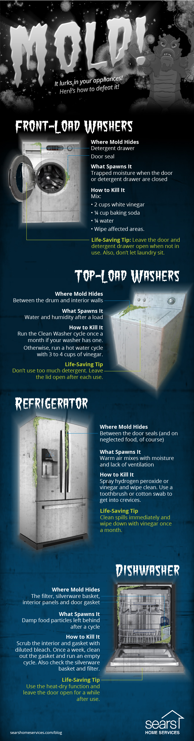
Where there’s moisture, there could be mold. Keep mold out of your washer, fridge and dishwasher with these tips.

Mold could be growing inside your appliances without your even knowing it. It can lurk in your washer, dishwasher or fridge — and that doesn’t mean artisan blue cheese. Simply put, mold grows where moisture lives, explains the Centers for Disease Control and Prevention (CDC), and since these appliances all work with water, they’re susceptible to mold growth.

What causes mold? Poor venting in appliances, leaks, clogged drains — and dare we say it? — user error.
Everyone knows mold is gross, but more than the yuck factor, it can do a number on your health, especially if you’re sensitive to it, according to the CDC. You can experience a variety of symptoms from exposure to mold, including a stuffy nose, coughing, throat irritation or skin irritation. If you have mold allergies, a chronic lung disease like asthma or a compromised immune system, you could experience even more severe reactions or an infection.
Health concerns aside, do you really want mold in the appliances you’re using to clean your clothes and dishes and store your food?
Fortunately, there are things you can do to help banish mold from your appliances. We’re breaking down the most common mold culprits and fixes, with help from Jeffrey McBride, an appliance expert at Sears Home Services. Remember to consult your owner’s manuals first for information on how to properly care for your specific appliances.


Mold in Your Appliances: Where It Grows and How to Get Rid Of It

Mold

Front-Load Washers


Where Mold Hides: The door seal and detergent drawer What Spawns It: Trapped moisture when the door or detergent drawer are closed

How to Kill It: Mix:

  • 2 cups white vinegar
  • 1/4 cup baking soda
  • 1/4 water
Wipe affected areas.
Life-Saving Tip: Leave the door and detergent drawer open when not in use. Also, don’t let laundry sit.


Top-Load Washers


Where Mold Hides: Between the drum and interior walls
What Spawns It: Water and humidity after a load

How to Kill It:


Run the Clean Washer cycle once a month if your washer has one. Otherwise, run a hot water cycle with 3 to 4 cups of vinegar.
Life-Saving Tip: Don’t use too much detergent. Leave the lid open after each use.


Refrigerators


Where Mold Hides: Between the door seals (and on neglected food, of course)
What Spawns It: Warm air mixes with moisture and lack of ventilation

How to Kill It:

Spray hydrogen peroxide or vinegar and wipe clean. Use a toothbrush or cotton swab to get into crevices.
Life-Saving Tip: Clean spills immediately and wipe down with vinegar once a month.


Dishwashers


Where Mold Hides: The filter, silverware basket, interior panels and door gasket
What Spawns It: Damp food particles left behind after a cycle.

How to Kill It:

Scrub the interior and gasket with diluted bleach. Once a week, clean out the gasket and run an empty cycle. Also check the silverware basket and filter.

Sunday, July 29, 2018

Reemplazo y Mantenimiento correctivo a un sistema de aire acondicionado y refrigeración.

Como remplazar un compresor.

  1. Desmontaje de piezas.
  2. Sacar los componentes eléctricos, desconectar el cable de encendido, sacar el relé y el protector térmico, también se hace necesario sacar el capacitor.

Pruebas eléctricas.

Enseguida también es necesario averiguar la continuidad eléctrica en el cable de encendido.

  • También se realiza lo mismo con el protector térmico verificamos su continuidad. 
  • La capacitancia del capacitor.
  • En el relay,  la verificación debe ser hecha en la bobina principal.
  • Bobina de arranque verificación de continuidad.
  • Continuidad en la bobina del compresor a través de los tres contactos del Compresor. haciendo prueba en 2 de cada fila.
  • Si muestra contactos abiertos es que el motor esta quemado, si mostró continuidad es que eso significa que el motor está en buen estado.
  • Al momento de desmontar el motor debe de liberar el fluido refrigerante.
  • Para liberar el refrigerante se necesita una válvula perforadora que se conecta en la tubería de servicio y abrir la válvula para liberar el fluido.

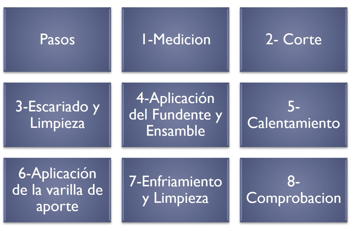
Soldadura en las líneas del compresor

  • Para soldar las líneas se tiene que lijar muy bien el cobre, esto facilitara el trabajo al momento de soldar.


Como  soldar cobre


Como remplazar un condensador de un equipo a/c

Instrucciones:
  • Apaga la alimentación de la unidad exterior a través de la desconexión eléctrica o del interruptor.
  • Retira la tapa del panel eléctrico del aire acondicionado quitando los tornillos que lo sujetan a la unidad.
  • Comprueba con tu voltímetro que el equipo está apagado al fijar tu medidor para medir el voltaje y tocando el extremo de la sonda en el lado principal del contactor.        
  • Aquí es donde los cables entran en la unidad.  Debes leer sin voltaje.
  • Utiliza un destornillador para conectar a tierra las terminales del condensador al gabinete metálico del acondicionador de aire. Esto descargará cualquier carga almacenada en el condensador. 
  • Anota los colores del cable, de dónde vienen y a qué terminal del condensador se conectan. También puedes comprobar el cableado de alimentación con el diagrama de cableado en la parte interior de la cubierta del panel.
  • Retira el tornillo de montaje que mantiene el condensador en su lugar. Utiliza tus alicates para quitar los cables. Lee la etiqueta de especificaciones del condensador y sustitúyela por una del mismo voltaje e índice de microfaradios. Por ejemplo: 35/5 mfd. @ 370 voltios.
  • Monta el condensador nuevo en lugar del viejo y asegura con el tornillo de montaje. Vuelve a conectar los cables de acuerdo con la forma en que los montaste en el condensador viejo.
  • Vuelve a colocar la cubierta del panel eléctrico y asegúrala con los mismos tornillos que quitaste antes. Re-conecta la energía a la unidad. 

Cómo reemplazar un evaporador de aire acondicionado

  • Asegúrate de que el aire acondicionado de ventana está desconectado de cualquier fuente de energía antes de comenzar a limpiarlo.
  • El condensador de tu unidad de ventana puede almacenar electricidad aun cuando el equipo esté desenchufado.
  • Retira la tapa del panel eléctrico del aire acondicionado quitando los tornillos que lo sujetan a la unidad.
  • Lee la etiqueta de especificaciones del condensador y sustitúyela por una del mismo voltaje e índice de microfaradios. 
  • Monta el nuevo condensador y vuelve a colocar la cubierta del panel eléctrico y asegurarla con los mismos tornillos que quitaste antes. 

Prueba de arranque.

Para verificar que todos los reemplazos realizados o por realizar se debe de realizar una prueba de arranque en donde se verificara que no haya algún problema en el equipo.

Wednesday, June 13, 2018

REFRIGERATION CYCLES PART 2

THE IDEAL VAPOR-COMPRESSION REFRIGERATION CYCLE

The vapor-compression refrigeration cycle is the ideal model for refrigeration systems, air conditions and heat pumps.

It consists of four processes:

1-2 Isentropic compression in compressor.

2-3 Constant-pressure heat rejection in a condenser.

3-4 Throttling in an expansion devise.

4-1 Constant-pressure heat absorption in an evaporator.

The  process  in  ideal  vapor  compression  refrigeration cycle:

The  refrigerant  enters  the  compressor  at  state 1 as saturated vapor and is compressed isentropically to the condenser pressure. The temperature of the refrigerant increases during this isentropic compression process to well above the temperature of the surrounding medium.

The refrigerant then enters the condenser as superheat vapor at state 2 and leaves as saturated liquid at state 3 as a result to the heat rejection to the surrounding. 

The saturated liquid at state 3 enters an expansion valve or capillary tube and leaves at  evaporator pressure.  The temperature of refrigerant drop below the temperature of  refrigerated  space  during  this  stage.  

The  refrigerant enters the evaporator at stage 4 as saturated mixture and it completely evaporate by absorbing the heat from the refrigerated space. The refrigerant leaves the evaporator as saturated vapor and reenters the compressor, completing the cycle.

ACTUAL VAPOR-COMPRESSION REFRIGERATION CYCLE

An actual vapor-compression refrigeration cycle differs from the ideal one owing mostly to the irreversibilities that occur in various components, mainly due to fluid friction (causes pressure drops) and heat transfer to or from the surroundings.

The COP decreases as a result of irreversibilities.

DIFFERENCES

  • Non-isentropic compression
  • Superheated vapor at evaporator exit
  • Subcooled liquid at condenser exit
  • Pressure drops in condenser and evaporator 
In the ideal cycle, the refrigerant leaves the evaporator and enters the compressor as saturated vapor.  In practice, however, it ·may not be possible to control the state of the refrigerant so precisely.  Instead, it is easier to design the system so that the refrigerant is slightly superheated at the compressor inlet.

This slight overdesign ensures that the refrigerant is completely vaporized when it enters the compressor. Also, the line connecting the evaporator to the compressor is usually very long; thus the pressure drop caused by fluid friction and heat transfer from the surroundings to the refrigerant can be very significant. The result of superheating, heat gain in the connecting line, and pressure drops in the evaporator and the connecting line is an increase in the specific volume, thus an increase in the power input requirements to the compressor  since steady-flow work is proportional to the specific volume.

The compression process in the ideal cycle is internally reversible and adiabatic, and thus isentropic.  The actual compression process, however, involves frictional effects, which may increase or decrease the entropy, depending on the direction.  

Therefore, the entropy of the refrigerant may increase or decrease during an actual compression process depending on which effects dominate.  The compression process may be even more desirable than the isentropic compression process since the specific volume of refrigerant and thus the work input requirement are smaller in this case.  

Therefore, the refrigerant should be cooled during the compression process whenever it is practical and economical to do so.

In the ideal case, the refrigerant is assumed to leave the condenser as saturated liquid at the compressor exit pressure. In reality, however, it is unavoidable to have some pressure drop in the condenser as well as in the lines connecting the condenser to the compressor and to the throttling valve. 

Also, it is not easy to execute the condensation process with such precision that the refrigerant  is a saturated  liquid at the end, and it is undesirable  to route the refrigerant  to the throttling valve before the refrigerant is completely condensed. 

Therefore, the refrigerant is subcooled somewhat before it enters the throttling valve. We do not mind this at all, however, since the refrigerant in this case enters the evaporator with a lower enthalpy and thus can absorb more heat from the refrigerated space. 

The throttling valve and the evaporator are usually located very close to each other, so the pressure drop in the connecting line is small.


Monday, June 11, 2018

REFRIGERATION CYCLES PART 1

In this article we are reviewing the factors involved in selecting the right refrigerant for an application.

REFRIGERATORS

The transfer of heat from a low- temperature region to a high-temperature one requires special devices called refrigerators.


Refrigerators are cyclic device, and the working fluids used in the refrigeration cycles are called refrigerants. 

HEAT PUMPS

Another   device   that   transfers heat from a low-temperature medium to a high-temperature one is the heat pump


Refrigerators and heat pumps are essentially the same devices; they differ in their objectives only. 

The objective of a refrigerator is to remove heat (QL) from the cold medium.

The objective of a heat pump is to supply heat (QH) to a warm medium.

The cooling capacity of a refrigeration system is the rate of heat removal from the refrigeration space  is often expressed in terms of ton of refrigeration.

The capacity of a refrigeration system that can freeze 1 ton of liquid water at 0 °C into ice at 0 °C in 24 h is said to be 1 ton.

VAPOR-COMPRESSION REFRIGERATION CYCLE

Two modes of operations:

1. Ideal vapor-compression refrigeration cycle
2. Actual vapor-compression refrigeration cycle


THE IDEAL VAPOR-COMPRESSION REFRIGERATION CYCLE

The vapor-compression refrigeration cycle is the ideal model for refrigeration systems, air conditions and heat pumps.

It consists of four processes:

1-2 Isentropic compression in compressor.

2-3 Constant-pressure heat rejection in a condenser.

3-4 Throttling in an expansion devise.

4-1 Constant-pressure heat absorption in an evaporator.

The  process in ideal vapor compression  refrigeration
cycle:

The  refrigerant  enters  the  compressor  at  state 1 as
saturated vapor and is compressed isentropically to the
condenser pressure. 

The temperature of the refrigerant increases during this isentropic compression process to well above the temperature of the surrounding medium.

The refrigerant then enters the condenser as superheat
vapor at state 2 and leaves as saturated liquid at state 3
as a result to the heat rejection to the surrounding.

The saturated liquid at state 3 enters an expansion valve or
capillary  tube  and  leaves  at  evaporator  pressure.  The
temperature of refrigerant drop below the temperature
of  refrigerated  space  during  this  stage.  

The  refrigerant enters the evaporator at stage 4 as saturated mixture and it completely evaporate by absorbing the heat from the refrigerated space. The refrigerant leaves the evaporator as saturated  vapor and reenters the compressor, completing the cycle.  

Notice that the ideal vapor­ compression refrigeration  cycle is not an internally reversible cycle since  it involves an irreversible (throttling) process. This process is maintained in the cycle to make it a more realistic model for the actual vapor­ compression refrigeration cycle. If the thronling device  were replaced by an isentropic turbine, the refrigerant would enter the evaporator at state 4´ instead of state 4. As a result, the refrigeration capacity  would increase and the net work input would decrease (by the amount of work output of the turbine). Replacing the expansion valve by the turbine is not practical since the added benefits cannot justify the added cost and complexity


SELECTING THE RIGHT REFRIGERANT

Several refrigerants may be used in refrigeration systems such as chlorofluorocarbons (CFCs), ammonia, hydrocarbons (propane, ethane, ethylene, etc.), carbon dioxide, air (in the air-conditioning of aircraft), and even water (in applications above the freezing point).

•    R-11, R-12, R-22, R-134a, and R-502 account for over 90 percent of the market.

•    The industrial and heavy-commercial sectors use ammonia (it is toxic).

•    R-11 is used in large-capacity water chillers serving A-C systems in buildings.

•    R-134a (replaced R-12, which damages ozone layer) is used in domestic refrigerators and
freezers, as well as automotive air conditioners.

R-22 is used in window air conditioners, heat pumps, air conditioners of commercial buildings, and large industrial refrigeration systems, and offers strong competition to ammonia.

R-502 (a blend of R-115 and R-22) is the dominant refrigerant used in commercial refrigeration systems such as those in supermarkets.

CFCs allow more ultraviolet radiation into the earth’s atmosphere by destroying the protective ozone layer and thus contributing to the greenhouse effect that causes global warming. Fully halogenated CFCs (such as R-11, R-12, and R-115) do the most damage to the ozone layer. Refrigerants that are friendly to the ozone layer have been developed.

Two important parameters that need to be considered in the selection of a refrigerant are the temperatures of the two media (the refrigerated space and the environment) with which the refrigerant exchanges heat.


Wednesday, June 6, 2018

REPAIR A AIR CONDICIONER - MAKE A SYSTEMATIC ANALYSIS


When an air conditioner failure, changing parts might be the first reaction, BUT...


  1. May not be necessary and...
  2. Does not always solve the problem


SUPERHEAT AND SUCTION PRESSURE

SYMPTOMS CAN PROVIDE THE REAL CAUSE.


1.       Moisture, dirt, wax

2.       Undersized valve

3.       High superheat adjustment

4.       Gas Charge condensation

5.       Dead thermostatic element charge

6.       Wrong thermostatic charge

7.       Evaporator pressure drop – no external equalizer

8.       External equalizer location.

9.       Restricted or capped eternal equalizer

10.   Low refrigerant charge

11.   Liquid line vapor

a.       Vertical lift
b.       High friction loss
c.       Long or small line
d.       Plugged drier or strainer

12.   Low pressure drop across valve

a.       Undersized distributor nozzle or circuits
b.       Low condensing temperature


1.       Oversized valve

2.       TEV seat leak

3.       Low superheat adjustment

4.      Bulb installation

a.       Poor thermal contact
b.       Warm location

5.       Wrong thermostatic charge

6.       Bad compressor – low capacity

7.       Moisture, dirt, wax

8.       Incorrectly located external equalizer


1.       Low load

a.       Not enough air.
b.       Dirty air filters
c.       Air too cold.
d.       Cool icing

2.       Poor Air distribution

3.       Poor Refrigerant distribution

4.       Improper compressor-evaporator balance

5.       Evaporator oil logged

6.       Flow from one TEV affecting another´s bulb


1   


© PARKER HANNIFIN CORP 2018